Project MoodJar: Aluminum Solder Joints
In my last post, Capacitive Touch Testing Platform, I experimented with soldering to aluminum. I had read about all kinds of tricks for such soldering: solder under oil, scratch the surface with a wire brush first, etc. I cheated and scratched the surface of the aluminum with the iron under a ball of solder. This post is just about the resistances of those joints, as well as some finishing touches on the CTTP.
Resistance of the Solder Joints
The Resistance of the solder joint's is shown below in Table 1. The row labeled "Control" was the resistance measured through the wires of the multi-meter with no load attached.
| Wire | Measurement [Ω] |
|---|---|
| Control | 0.2 |
| Black | 0.5 |
| Orange | 0.5 |
| Yellow | 0.4 |
| Green | 0.5 |
| Blue | 0.4 |
| White | 0.5 |
As you can see, the joints are showing almost no resistance. They are only about 0.3 Ω at most. This leads me to conclude that its perfectly fine to solder to aluminum foil using the "cheating method."
Finishing Touches
As for the finishing touches: quite simply, I soldered the leads of CTTP to some header pins (Figure 1) for easier use with a breadboard. I also braided the wires and heat-shrunk them near the board (Figure 2) because it always looks nicer and stores more easily that way.
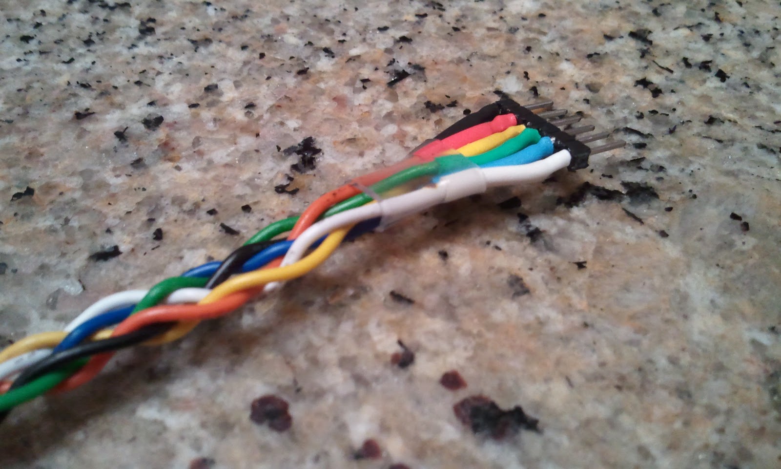 |
| Figure 1: Wires of the CTTP updated for breadboard compatibility |
 |
| Figure 2: Braided and heat-shrunk wires leaving the CTTP |
Sure, its a tad excessive, but it looks nice.
Next I want to do some experiments with the Arduino and this CTTP. I'd like to coat 4 of them with a couple different materials for testing.
Next I want to do some experiments with the Arduino and this CTTP. I'd like to coat 4 of them with a couple different materials for testing.


Comments
Post a Comment
Please keep your comments respectful and in the spirit of constructive criticism.