Project MoodJar: Capacitive Touch Testing Platform
I've been working on a project for a while now... about a year or more. Originally, I was going to call it SunJar, but that concept has already been developed and sold, and I intend to incorporate more functionality. And color. So it is going to be called MoodJar.
Anyway, the last post I had on it was quite some time back, when I talked about solar cell characteristics. This post is going to be about the capacitve-touch I intend to incorporate.
Intro to Capacitive Touch
If you already know how capacitive touch works, you can skip this section. I just thought I would give a short and simple explanation of how it works for those who don't.
Essentially, everything around us has some sort of capacitance related to it. Capacitance is a measure of how quickly positive or negative charges build up. When you link different capacitors together, it changes the capacitance of the entire configuration. For example, if you touch a piece of metal, your capacitance will be combined with the capacitance of the metal in some fashion, and the time it takes for the metal to reach a certain amount of charge will be distinguishable from the amount of time it takes when you are not touching the metal. For smartphone screens, it is a bit more complex because they need to locate where on the screen you are touching, but this is the basic principle behind capacitive sensing.
Since I will be using an Arduino, at least for my developement, I would recommend you read this article. I will likely use this library, unless I need any modifications.
Capacitve Testing Platform
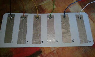
I wanted to make a platform to use when I am testing the logic of my MoodJar project. To do this, I cut out a piece of cardboard and super-glued six strips of aluminum to one side with the intent of soldering wires to each piece of foil which I could plug into a breadboard.
 |
| Nearly finished Capacitive-Touch sensing Platform |
It turns out that it is pretty difficult to solder to aluminum. The reason for this is that it very quickly, especially when hot, forms a transparent oxide layer that resists soldering. I read about all kinds of methods for overcoming this. One such suggestion was to scratch the surface with a wire brush and a layer of oil to prevent oxidation, and then solder underneath the oil.
I didn't have the time to get all those supplies, but what I did instead was to drop a large ball of solder on the foil, and then scratch the surface of the foil underneath the molten ball of solder with the tip of the soldering iron. Of course, this lead to some burning of the solder's flux, but eventually the ball of solder started to stick to the foil instead of roll away. Then I just added the wire to the ball of solder and made sure the connection was sufficient with a multimeter.
 |
| Close up of Solder Joints; Joints 1-6 from left to right, top to bottom |
I'm not sure how the process of soldering those joints affects their electrical properties, but I might post some resistances later, just for comparison. After all the work was done, I also covered the joints with some epoxy, because I don't want them coming loose. They seemed pretty sturdy, though.
Update
For resistance data, see Aluminum Solder Joints.

Comments
Post a Comment
Please keep your comments respectful and in the spirit of constructive criticism.